









A carton printing plant called us about a compressor they were convinced was dying. Three years old, correct size on paper, and yet the pressure gauge at the far end of the building read just over 6 bar while the machine sat at 8. They’d already replaced the air end once. That cost them a four-day shutdown, and it fixed nothing, because the compressor was never the problem.
The problem was 40 metres of 1-inch pipe.
Nobody has strong feelings about pipework. It gets specified by whoever is doing the fit-out, sized by eye (“we used the same stuff last time”), and then forgotten. Meanwhile it quietly eats the pressure you paid for. And pressure is expensive. Every bar you lose in the line is a bar your compressor has to make again, forever, every operating hour.
This guide covers how to size compressed air pipe properly: start from flow, pick a target pressure drop, then read a table and round up. No fluid dynamics degree needed.
Why pipe sizing is always the thing nobody does
It isn’t laziness. It’s a scheduling accident.
The compressor is bought months before installation. Nobody knows exactly where the tools will sit, someone adds a machine, someone else moves the packing line, and the pipe gets run to whatever is convenient. Six years later the plant has doubled its air demand and the distribution is still sized for the original setup.
Three things make it worse:
- Air demand grows. Almost every plant we visit uses more compressed air than it did five years ago, and almost none of them re-sized the pipe when it did.
- Pressure creep. When tools start underperforming, the default fix is to turn up the compressor pressure. That buys performance at the far end and costs money at the compressor — roughly 7% more energy for every extra bar, indefinitely.
- Nobody measures at the point of use. Nearly every plant we visit can quote receiver pressure. Very few can quote pressure at the worst tool during a peak draw. That’s the only number that matters.
The good news: if you’re designing a new system, getting this right costs almost nothing. Pipe one size larger is a rounding error in a compressed air project budget. Fixing it later means cutting the old pipe out.
Pressure drop, without the theory
Air moving through a pipe loses energy to friction against the pipe wall, plus turbulence at every fitting, valve, bend and reducer. That lost energy shows up as lower pressure downstream.
Three rules cover 90% of practical decisions:
- Drop rises roughly with the square of flow. Double the flow through the same pipe and the drop doesn’t double either. It roughly quadruples. This is why adding one machine to a borderline system tips it over.
- Length scales linearly. Twice the pipe length, twice the drop, same flow.
- Diameter matters enormously. Increasing pipe diameter has a far stronger effect than almost anything else you can change. Going up one nominal size typically cuts the drop to a third or less.
The target most suppliers work to: keep total distribution loss under about 0.3 bar from the compressor discharge to the furthest point of use, at design flow. If you’re running at 7 bar, that’s roughly 5% of operating pressure — enough that the tool doesn’t notice, small enough that you’re not wasting real energy.
Keep your header velocity in the region of 8–15 m/s. Above 20 m/s you’re paying for it in noise, erosion at bends and pressure drop, and there’s rarely a reason to be there.
Flow first: how much air actually moves
Before you can size anything, you need flow at your actual working pressure. Not the number on the compressor nameplate, though. Your actual consumption.
Two ways to get it:
Bottom-up. List every air consumer, its rated consumption and how long each actually runs per shift. This is tedious and it’s also the most useful hour you’ll spend on the project, because it usually shows the nameplate total is wildly pessimistic. Ten machines rated at 100 L/min each don’t draw 1,000 L/min together; three of them come on at once, most of the time. That difference is called the diversity factor, and arguing about it is the single most common disagreement in compressed air design. If you’re unsure, 0.6–0.8 is a reasonable starting assumption for general manufacturing.
Top-down. If you already have a system, watch how fast pressure falls during a peak, or better, borrow a flow meter for a week. A week of data beats any calculation, and it’ll also show you how much of your demand is leaks — which is its own article.
Convert everything into free air delivered in m³/min (or CFM if you’re working in imperial) at your design pressure. Then size to peak concurrent flow, not average flow. Pipe has to cope with the moment everything comes on at once.
Reading a pipe sizing table
The table below gives indicative capacities for flow at 7 bar(g) with roughly 0.3 bar drop per 30 m of straight steel pipe. It’s a rule of thumb, not a specification; your pipe supplier’s own chart will differ a bit and should win.
| Nominal size (DN) | Inch | Approx. capacity (m³/min) | Approx. capacity (CFM) |
|---|---|---|---|
| DN15 | ½” | 0.6 | 20 |
| DN20 | ¾” | 1.3 | 45 |
| DN25 | 1″ | 2.5 | 90 |
| DN32 | 1¼” | 5.0 | 180 |
| DN40 | 1½” | 8.0 | 290 |
| DN50 | 2″ | 17.5 | 620 |
| DN65 | 2½” | 31 | 1,100 |
| DN80 | 3″ | 54 | 1,900 |
| DN100 | 4″ | 105 | 3,700 |
So the plant at the top of this article — say 90 kW of screw capacity plus peak demand around 12 m³/min — needed DN50 minimum on the figures above. They had DN25 running 40 metres to the far wall. It was never going to hold pressure, no matter how good the compressor was.
Two practical notes on using the table:
- If you land between sizes, go up. Pipe is cheap once; pressure loss is paid for every hour for twenty years. I have never once seen a plant regret going up a size.
- Fittings count. Those capacities are for straight pipe. Real systems have elbows, tees, valves and couplings, and each one adds friction equivalent to a length of pipe. A practical shortcut is to add the equivalent length of your fittings — a 90° elbow adds roughly the equivalent of a metre or two of straight pipe depending on size — or simply derate table figures by 25–30% for a typical installation with lots of bends.
Layout matters more than people think
Two systems can use the same pipe size and behave completely differently because of how they’re laid out.
Dead-end versus ring main. A single dead-end header fed from the compressor is simple and cheap, and it’s fine for small systems. A ring main loops around the building and returns to the compressor, so air reaches every drop point from two directions. The effect: each section carries roughly half the flow, effective distance halves, and pressure stays much more even as different areas switch on and off. For anything beyond a small workshop with a handful of drops, the ring is worth it.
Drops off the top. Take branch connections from the top of the header, not the bottom, and rise before turning down to the drop point. Water travels along the bottom of the pipe (there’s always some), and a bottom take-off is an invitation to send it straight into your tools. Combine it with a drain leg at low points and you’ll avoid most water complaints before they start.
Slope the header. Roughly 1–2% fall in the direction of airflow, with automatic drains at every low point. It costs nothing to do while the pipe is going up and is nearly impossible afterwards.
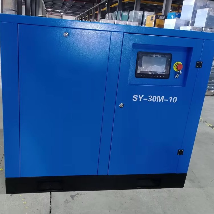
Keep future capacity in the header. If a second compressor is plausible in five years, size the header for it now. Adding machines to an undersized ring main later is how plants end up with three separate systems that don’t work well together. If demand is climbing, variable-speed capacity helps on the machine side too — the VSD 22 kW screw compressor tracks a varying load far better than a fixed-speed unit cycling on and off.
Fittings, hoses and couplings: the half nobody counts
Here’s where a lot of careful pipe sizing gets thrown away. I’ve seen plants with beautifully sized steel header feeding everything through eight metres of 6 mm hose, then wondering why the tool is weak.
A few things that catch people out:
- Hose bore is the usual culprit. Cheap hose with a small bore can lose more pressure in five metres than forty metres of correctly sized steel pipe. Where tools need real flow, match hose bore to the tool inlet, and keep runs short.
- Quick-connect couplings. Every one is a restriction in series. Older-style industrial couplings are considerably worse than modern high-flow profiles. If you have a standard coupling type across the plant, upgrading it is often cheaper than upgrading anything else.
- The last metre. Reducers, elbows at the drop point, an old filter with a clogged element, a half-closed ball valve someone fitted for maintenance and never reopened. Walk the line before you blame the compressor. Our piece on pressure drop causes and solutions goes through this systematically.
- Filters and dryers have their own differential. A new filter might be 0.1 bar; a neglected one can be several times that. Include quoted ∆p figures at your actual flow, and note whether they’re quoted clean or dirty. They usually are quoted clean.
Rule of thumb for tooling: count fittings as pipe. A cluster of ten elbows is not detail. It’s a meaningful chunk of your loss budget.
Materials: what to run, and what not to
| Material | Worth knowing |
|---|---|
| Black steel | Traditional industrial choice. Strong, handles pressure and heat, needs painting and will rust internally over time if water sits in it. Cheapest per metre. |
| Galvanised | Better corrosion resistance than black steel, but the zinc has a habit of flaking if the pipe is bent or threaded badly. |
| Aluminium | Increasingly common for compressed air. Smooth bore (less friction), no rust, light, quick to install with push-fit systems. Costs more per metre, installs much faster. |
| Stainless | The answer where air quality genuinely matters, food and pharma especially. Expensive and usually specified for cleanliness rather than pressure reasons. |
| Copper | Fine for small workshop drops, costly and unnecessary for large headers. |
| PVC / plastic | Don’t. Even when the pressure rating looks adequate, plastic becomes brittle with age and temperature cycling, and a compressed air line failure is not like a water leak. It stores energy. Several safety codes specifically exclude it for compressed air. |
Whatever you pick, keep it clean during installation. We’ve opened new lines with weld slag and a dead rag still inside. It ends up in a solenoid valve, and then it’s a mysterious intermittent fault for the next two years.
A sizing checklist you can actually run
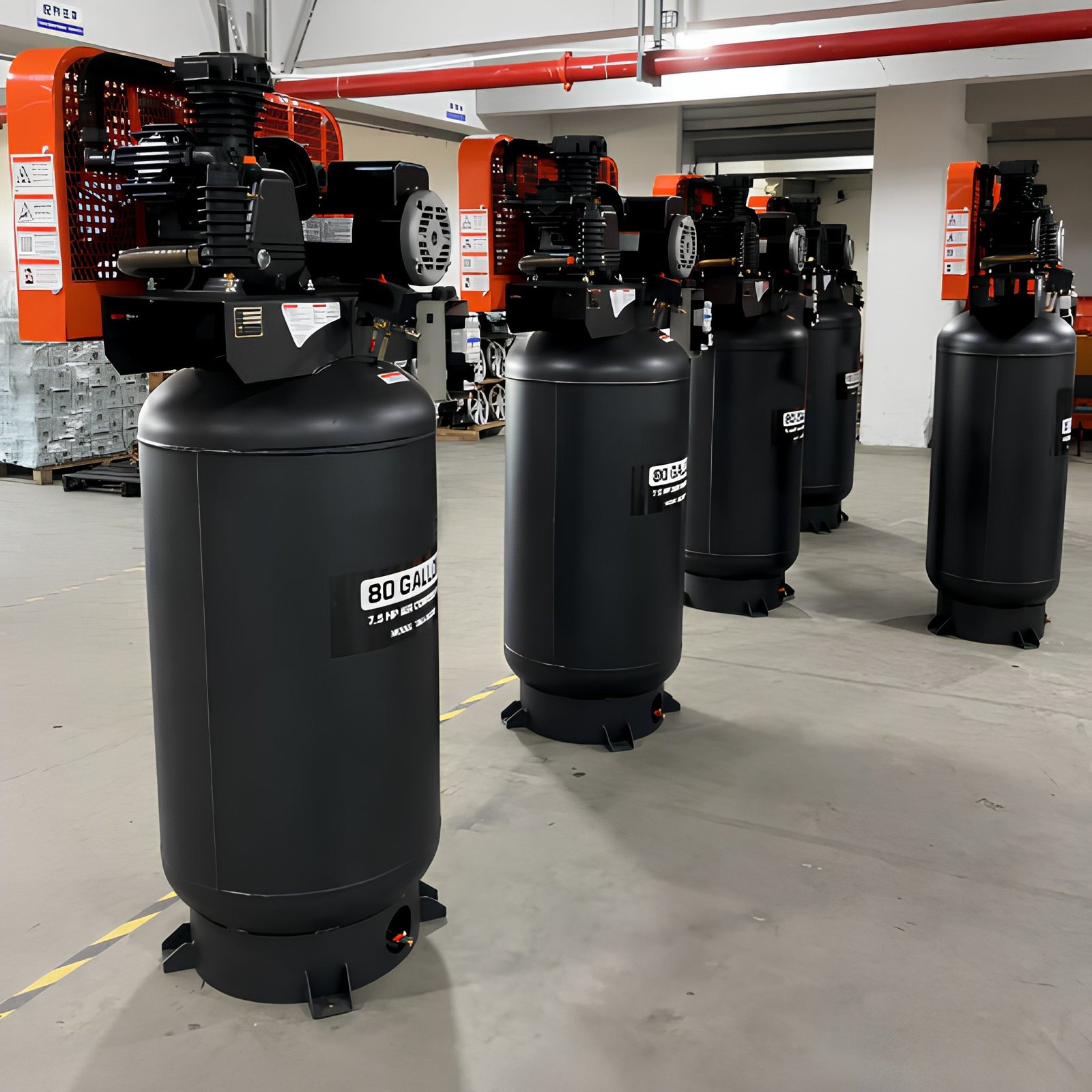
One more thing worth deciding before you start: how much receiver volume you want to sit between the compressor and the header. Storage covers short peaks so the compressor doesn’t have to, and it smooths the pressure swings that make tools feel weak. Tank-mounted packages solve it in one footprint — this 7.5 HP piston unit with an 80-gallon receiver is the classic small-workshop arrangement.
Run these in order:
- Measure demand at the point of use, or build it bottom-up with an honest diversity factor.
- Set the target. No more than about 0.3 bar loss across the whole distribution at peak flow.
- Size the header from the table at peak concurrent flow, then go up one size if you’re between sizes or expect growth.
- Add fitting equivalent lengths, or derate by 25–30% for a typical bend-heavy layout.
- Choose ring main over dead-end where the building allows it.
- Take drops from the top of the header, with a short rise before the downturn.
- Slope and drain. Aim for 1–2% fall with automatic drains at every low point.
- Match hose and couplings to tool requirements, and budget for high-flow profiles.
- Record the design. Note pipe sizes, lengths and target flows on a drawing. Future you will need it when someone wants to add a machine.
If any step feels like guesswork, send us the layout through the página de contacto and we’ll check the numbers. It takes about twenty minutes and it’s much cheaper than replacing an air end because of pipework.
And if you’re still specifying the compressor itself, our installation guide and the broader industrial compressor buyer’s guide cover the upstream decisions this pipework has to serve.
Preguntas frecuentes
What size compressed air pipe do I need for a 22 kW compressor?
It depends on pressure and where the air goes, not just motor power. A 22 kW screw unit at 7–10 bar produces somewhere in the region of 3–4 m³/min, so DN40 – DN50 would typically be the header choice for a normal length run. Our 22 kW single-stage screw compressor page lists its output — size from that figure, not from kilowatts.
Is ½” pipe enough for a small workshop?
Up to roughly 0.6 m³/min at short distances, yes. That’s a couple of impact guns or a spray gun, not sustained use. Most single-tool workshops are better served by ¾” for the header with ½” drops, because the price difference is small and the future flexibility is real.
Can I just raise the compressor pressure instead?
You can, and plenty of plants do. But raising output to cover distribution losses typically costs around 7% extra energy per bar, every hour the plant runs, and it also pushes up leak rates and wear. Compare that against the one-off cost of larger pipe and it usually isn’t a close call.
Should I use aluminium or steel?
If labour cost matters and the work is inside, aluminium usually wins these days: smoother bore, faster install, no rust particles. If the line is going outside, gets knocked about, or budget dominates short install times, black steel is still perfectly defensible. Both work; both have been overspecified and underspecified plenty of times.
Do I need to replace existing undersized pipe?
Not always. Adding a parallel run, changing the layout to a ring main, or fixing the hose and coupling restrictions can recover a surprising amount. Measure pressure at the worst point during a peak draw before committing to a rip-out — we’ve seen many “undersized pipe” problems turn out to be a clogged filter.
Ready to look at hardware rather than pipe? Browse the screw compressor range, piston range or oil-free scroll range, or read about reducing the other half of your losses in our guide to compressed air energy efficiency.